Adjustments to spur gear backlash 600E GTO
|
Motor rotational motion is transmitted to the worm assembly by a spur gear set. If the worm is in good contact with the worm wheel and no backlash is felt on the axis, but there is excessive delay when reversing either RA or Dec direction, then it is possible that the two spur gears are not properly in mesh. |
|
|
Background Images
|
|
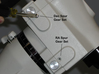 |
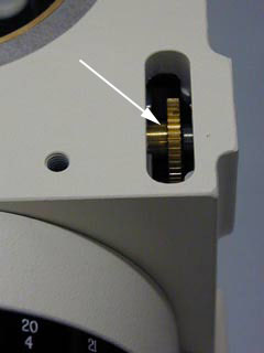
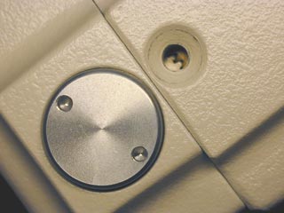
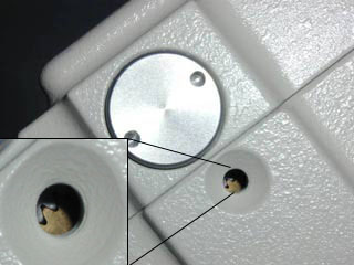
Removing the two stainless steel screws reveals the sight-hole which allows you to check the RA and Dec spur gear mesh. |
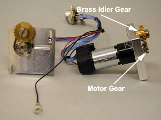 |
The motor mount plate supports a stainless spur gear on the motor and a brass idler gear. |
 |
|
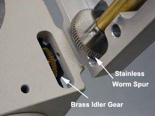 |
When the worm assembly is added the brass idler gear and the stainless worm spur will be meshed. The motor can now turn the worm and worm wheel through the spur gears. |
|
Spur
gear adjustment - Right Ascension (R.A.) axis
|
|
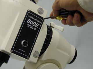 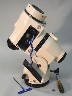 |
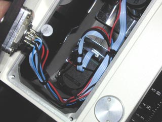
Step 1 Remove the nameplate by taking out the four M3 x 10mm phillips head screws, using a P1 phillips head screw driver.Let the name plate hang freely by the motor harness wires. |
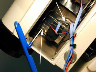 |
Step 2 Using a 3mm 6" (15 cm) long "T" handle hex tool, loosen each of the two screws that hold the square aluminum motor mount plate to the housing. The R.A. motor is the lower motor in the housing. |
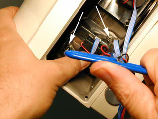  |
Step 3
Reposition the motor mount plate to engage the spur gears. Hold the
plate in place and lock down the socket head cap screws with the 3mm
hex tool. |
 |
Step 4
Power up the 600E control system and allow the motor to rotate at the
sidereal rate, 1 to 2 rotations. 1 rotation will take about 5 minutes.
If the overload LED does not glow amber, or no motor stall occurs the
adjustment is a success. Note: Only the control boxes shipped after February 16, 2000 have the red/amber overload LED's. |
 |
Step 5 Remount the cover plate with the phillps head screws, taking care to place the wires under the R.A. motor. This will position the wires out of sight of the polar alignment scope. |
|
Spur gear adjustment - Declination (Dec.) axis |
|
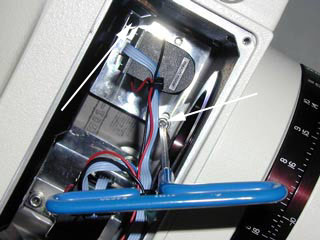 |
Step 1 Using a 3mm 6" (15 cm) long "T" handle hex tool, loosen each of the two screws that hold the square aluminum motor mount plate to the housing. The Dec. motor is the upper motor in the housing. |
  |
Step 2
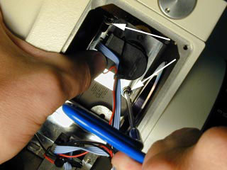
Reposition the motor mount plate to engage the spur gears. Hold the
plate in place and lock down the socket head cap screws with the 3mm
hex tool. Remove the upper
sight-hole screw. This will allow you to see if the brass idler gear
and the worm spur gear have properly been meshed. Make adjustments until
they do. |
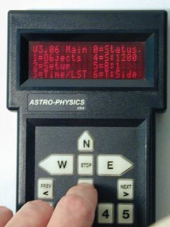 |
Step 3
Power up the 600E control system and manually slew the Dec. motor at
1x long enough to completely rotate the spur gears 1 to 2 times. If
the overload LED does not glow amber, or no motor stall occurs the adjustment
is a success. Note: Only the control boxes shipped after February 16, 2000 have overload LED's. |
 |
Step 4 Remount the cover plate with the phillps head screws, taking care to place wires under the R.A. motor. This will position the wires out of sight of the polar alignment scope. |
Home
Back to Technical Support Index
Copyright © 2004, Astro-Physics, Inc. - All Rights Reserved
This page was last modified:
April 28, 2004
Astro-Physics, Inc.
11250 Forest Hills Road, Rockford, IL 61115, U.S.A.
Phone: 815-282-1513 Fax: 815-282-9847